FAQs

01. What is a cable cleat?

A cable cleat is a cable restraint device (sometimes called a cable block, cable bracket or cable clamp) that is designed and tested to provide securing and retention of cables.  A cable cleat is typically fixed to a mounting surface (e.g. ladder-type cable tray rung) and fastened around one or more cables.  According to IEC 61914 and UL 2239, neither conduit clamps, P-clamps or cable ties are considered to be cable cleats.  Cable cleats may be applied to single conductor or multi-conductor cables.


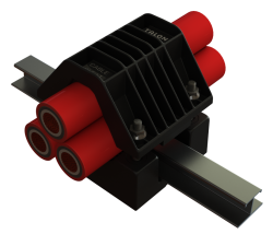
Talon® T3 Cable Cleat

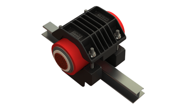
Talon® T1 Cable Cleat


In addition to securing cables subject to axial, lateral and torsional forces, Talon® cable cleats provide strain relief for vertical cables and protect high voltage, medium voltage and low voltage cables from mechanical damage resulting from short circuits.  Talon® cable cleats utilize a high-strength interlocking frame that simultaneously encloses cables and a support rung.  Only Talon® cable cleats — Hold the cables. Hug the Rung.®

02. Are cable clamps the same as cable cleats?

While the terms clamp and cleat are sometimes used interchangeably, they are governed by different standards with exclusive, but analogous test protocols (see FAQ-10).  The most important consideration when evaluating cable restraint products is to ensure the testing is applicable to cables (not pipe or conduit) and is performed under conditions that are at least as demanding as the intended usage.

Talon® cable cleats have passed rigorous 3rd party testing in accordance with ASTM B117, IEC 60695, IEC 61914, ISO 4892-2, UL 94 and UL 2239.

03. What is the difference between non-rigid and rigid cable cleats?

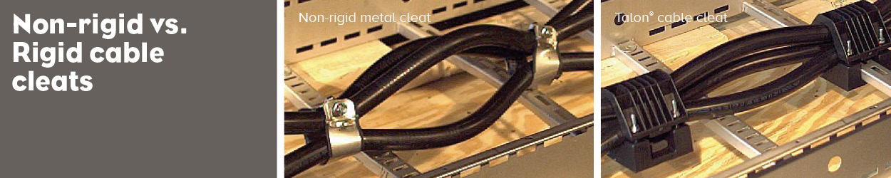
The left photo of legacy non-rigid cable cleats was taken 1.3 msec after the initiation of a 111 kAPEAK 3-phase short circuit test on single conductor 500 kcmil cables in cable tray.  The right photo depicts Talon® cable cleats during a similar short circuit test (i.e. 121 kAPEAK on same cables with identical lineal cable cleat spacing and photo timing).  The rigid design of Talon® cable cleats limits cable deflection and restrains cables subject to axial, lateral and torsional forces.  Additionally, Talon® cable cleats successfully passed the IEC 61914 axial resistance test after multiple short circuit tests.

One characteristic of non-rigid cable restraints is their increased propensity to deform under mechanical stress.  Cable restraints, including cable cleats, are classified as “non-rigid” when manufactured from ductile materials (e.g. metal banding) that can deform significantly and permanently when exposed to static or dynamic cable forces.  The left photograph demonstrates the severe limitations of non-rigid cable cleats.

Cable cleats classified as “rigid” retain their physical shape when exposed to static and dynamic mechanical stresses.  Rigid cable cleats are typically manufactured from non-ductile materials (e.g. heavy metallic cross-section or reinforced thermoplastic).  Thick stainless steel cross-sections are impractical due to high cost and other metals are unrealistic due to localized induction heating, corrosion susceptibility and/or poor product designs.  Fortunately, due to technological advances in non-metallic materials and their natural immunity to galvanic corrosion, cable cleats manufactured from high-strength reinforced thermoplastics are rapidly replacing legacy products.  Talon® cable cleats utilize a high-strength interlocking frame that simultaneously encloses cables and a support rung and do not suffer permanent deformation during testing.

04. Why are cable cleats required?

Unrestrained vs. Restrained Cables

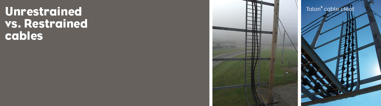
The left photo depicts unsupported cables resulting from cable tie failures.  On the right the cables are properly restrained by Talon® cable cleats.

Cable cleats are required for the securing and retention of cables.  This protection is especially important when cables are exposed to axial, lateral or torsional forces, such as those caused by the weight of cables in vertical runs or short circuit fault currents.  From a regulatory compliance perspective, proper cable retention facilitates conformance to electrical installation standards.  For example, NFPA-70-2017, The (US) National Electrical Code, NEC Article 392.20 (C) requires single conductors to be “securely bound in circuit groups to prevent excessive movement due to fault-current magnetic forces.”  In that same Code, Article 110.36 requires insulators used as supports for single conductor cables to be “capable of safely withstanding the maximum magnetic forces that would prevail if two or more conductors of a circuit were subjected to short circuit current.”  Other national wiring standards contain similar provisions for cable retention and protection from electromechanical forces.

Some installers mistakenly place cables in clamps that are designed for pipe or conduit, or they improperly apply cable ties or banding and damage the cable sheath or compress the insulation.  Electrical inspectors should be vigilant about correcting such misapplications to ensure cables are restrained by products that are tested and suitable for the application and provide long-term cable protection.

05. Where are cable cleats required?

Talon® cable cleats secure cables subject to lateral and torsional forces and provide axial strain relief for vertical and horizontal cables. Typical installations benefiting from Talon® cable cleats are:

  • Low, medium and high voltage, ac and dc systems
  • Single-conductor cables, including single cable and bundled cable configurations (e.g. trefoil, quad, etc.)
  • Multi-conductor cables susceptible to “through-faults”
  • Cables in extreme environments (e.g. arctic, desert, high altitude, offshore/marine, tropical, underground)
  • Cables exposed to aggressive forces (e.g. short circuits, cyclical loading, high-shock, pulse loads, seismic movement, vibration)
  • Vertical cables requiring strain relief and long straight cable runs (esp. cables in cable tray or cable racks)
  • Cables in manholes or vaults
  • Retrofit applications on unrestrained cables resulting from loose cable ties or permanently deformed non-rigid cleats/clamps
  • Any installation where an engineer or design professional must certify the cable system’s performance

06. What happens to cables during a short circuit?

Since alternating current follows a repetitive oscillating (sinusoidal) pattern, short circuit current produces alternating attractive and repulsive forces between conductors.  These dynamic electromechanical forces are constantly changing in magnitude and direction and can exceed 40 kN/m (2,741 lbf/ft).  Even when the short circuit current is quickly interrupted, it is important to recognize the maximum electromechanical forces typically occur within the first half cycle, which is long before a circuit breaker can open.  During a short circuit, the high current flowing through the conductor’s resistance rapidly heats the cable, resulting in axial (longitudinal) and lateral (radial) thermal cable expansion.  The combination of thermal expansion and electromechanical forces causes cable deflection (bowing/ bending), producing an axial strain on the cable terminations.  If a cable termination fails before the short circuit is interrupted (a typical failure mode on under-restrained cables), the cable can whip uncontrollably until the current is extinguished, risking further electrical and mechanical damage, as well as unleashing other safety concerns.

Optimum cable protection is provided when the electromechanical and thermal expansion forces are controlled and do not result in cable restraint deformation, stressed cable terminations, damaged cable tray, etc.  Cables that are exposed to potential short circuit current should be restrained by Talon® cable cleats.  Talon® cable cleats protect high voltage, medium voltage and low voltage cables from mechanical damage resulting from short circuits.

07. How can I calculate electromechanical forces between conductors?

Short Circuit Current Waveform

Example short circuit waveform (42kARMS-SYMM, 111.8kAPEAK)

The Lorentz Force Law may be used to calculate the electromechanical force between conductors, as follows:

F/l = μ0 * i1 * i2 / 2πs

Where:

F/l = Distributed force between conductors
F = Electromechanical force
l = Lineal spacing between cable restraints
μ0 = Magnetic permeability constant
i1 = Instantaneous current magnitude in conductor #1
i2 = Instantaneous current magnitude in conductor #2
π = pi (mathematical constant representing the ratio of a circle’s circumference to its diameter)
s = Spacing between conductor centers

Most alternating current short circuit waveforms involve asymmetry due to transient and subtransient reactance, as well as unidirectional current contribution (i.e. dc offset).  As such, the most appropriate calculation for short circuit electromechanical forces between two conductors is the Lorentz Force Law.  Since the Lorentz Force Law considers two conductors, basic mathematical techniques may be utilized to solve for three or more conductors.

CAUTION: Equations that are based on the RMS or peak current magnitude in only one conductor are erroneous and should not be used for calculating forces between cables during an alternating current short circuit (i.e. where the short circuit includes asymmetrical current).  IEC 61914:2015 warns readers of this severe limitation.  Talon Products is pleased to assist with your cable force calculations utilizing our proprietary cable force calculation software.

LINEAL SPACING

Lineal cable cleat spacing decisions are based on the dynamic electromechanical forces between cables, cable deflection, axial retention (i.e. strain relief) requirements and the geometry of the cable support system.  Talon Products is pleased to assist with cable force calculations utilizing our proprietary software.  The results of the force calculations will allow customers to choose a lineal spacing that fits their unique application.

CAUTION: Some cable cleat spacing charts may only consider the results of the IEC 61914 static cable cleat lateral resistance test, which (in the case of non-rigid cable restraint designs) may include severe cable cleat deformation.  Others may be based on an extrapolated force calculation that is erroneously based on the RMS or peak current magnitude in only one conductor (see FAQ-7).  Some spacing charts may similarly disregard dynamic cable cleat strength and other critical factors such as cable protection, cable deflection, strain relief requirements and potential damage to the cable support system.  During short circuit conditions, cable cleats are subjected to alternating attractive and repulsive forces between conductors.  Therefore, cable cleats must be designed and tested to withstand multiple applications of dynamic force during an extremely short time period; not just a single static lateral pull test.

HORIZONTAL (i.e. side-by-side) SPACING

Horizontal cable cleat spacing decisions are based on cable ampacity requirements, spacing between the cables and the width and load distribution of the cable support system.  National wiring standards like the (US) National Electrical Code provide cable ampacity tables that account for the mutual heating between conductors.  For example, in order to achieve the published ampacity without thermal cable damage, trefoil cable bundles are separated from adjacent conductors with a free airspace of 2 to 2.15 times the cable diameter of the largest cable.  With their patented rigid cable cleat design that simultaneously encloses cables and a support rung, Talon® T3 cable cleats installed side-by-side will comply with this spacing factor for cable diameters greater than ∅31 mm (1.22 in).  For smaller cables or lower spacing factors, the cable cleats may be staggered on adjacent rungs (an industry “best practice” that is favored by many installers, even when ample cable tray space is available).

09. Aren’t electrical cables protected by circuit breakers or fuses?

While circuit breakers and fuses can provide thermal protection for the cable insulation, they are unable to protect cables from mechanical damage.  Even with overcurrent protection devices that offer an “instantaneous” protection setting, irreversible cable damage will typically occur in inadequately restrained cables within the first half cycle of the fault initiation (i.e. before circuit breakers can interrupt the fault).  In the case of fuses, the restraint system must withstand the forces associated with the maximum let-through current.   In most cases, overcurrent protective devices for power cables are adjusted with intentional time-delay for system coordination with downstream devices, which increases the potential for mechanical damage in inadequately restrained cables.

All cables that are exposed to potential short circuit current should be restrained by Talon® cable cleats.  Talon® cable cleats protect high voltage, medium voltage and low voltage cables from mechanical damage resulting from short circuits.

10. What are the relevant standards for cable cleats?

IEC 61914 EDITION 2.0, 2015, CABLE CLEATS FOR ELECTRICAL INSTALLATIONS

The international cable cleat standard IEC 61914 provides testing criteria and requires cable cleats to protect the cables during short circuit testing.  To comply with the standard, products must pass tests for resistance to flame propagation, impact and ultraviolet light exposure, as well as for lateral retention.  The standard includes optional tests for axial retention and resistance to electromechanical forces.  The president of Talon Products, Charles Darnell, a Registered Professional Electrical Engineer, IEEE Senior Member and member of ANSI US National Committee of the IEC is the US Representative to the IEC subcommittee responsible for the maintenance of IEC 61914.

NOTE: IEC 61914 Edition 2.0 clarifies that Annex B equations B.5, B.6 and B.7 should not be used to extrapolate short circuit test results.

UL 2239/ CSA C22.2, STANDARD FOR HARDWARE FOR THE SUPPORT OF CONDUIT, TUBING AND CABLE

This harmonized standard includes tests for resistance to flame propagation, impact and ultraviolet light exposure, as well as for lateral retention.

OTHER STANDARDS

As a result of the global acceptance of cable cleats, several codes, standards and recommended practices have adopted increased cable restraint performance requirements.  Among these documents are API RP14F and RP14FZ, as well as IEEE Standards 45.8, 1185, 1242 and 2740.

GLOBAL COMPLIANCE

Talon® cable cleats have been independently tested in accordance with UL 2239 and IEC 61914, including the tests for axial retention and resistance to electromechanical forces during multiple successive short circuits. Talon® cable cleats comply with the rigorous cable restraint requirements provided in API RP14F, API RP14FZ, IEEE 45.8, IEEE 1185, IEEE 1242, IEEE 2740 and NFPA-70 (NEC).

11. What information is required to specify and purchase Talon® cable cleats?

Please furnish as much of the following information as possible:

    GENERAL DETAILS

  • Name and location of project
  • Estimated quantity of cleats, if known
  • Forces acting on cables (e.g. axial, high-shock, seismic, short circuit, thermal expansion, vertical strain relief, vibration, etc.)
    SYSTEM DETAILS

  • Operating voltage
  • ac (alternating current) or dc (direct current)
  • Power frequency (50 Hz or 60 Hz)
  • 1-Phase or 3-Phase
  • Maximum available fault current and associated electrical parameters (e.g. IRMS-SYM, IRMS-ASYM, IPEAK, etc.)
  • Maximum duration of fault current
    CABLE DETAILS

  • Quantity of cables in each cleat
  • Conductor cross-sectional area (AWG, kcmil, or mm2 for each cable)
  • Cable diameter (outside diameter of each cable)
  • Proposed center-to-center spacing between adjacent phases (if one cable per cleat)
  • Configuration of cables (e.g. straight or plexed)
  • Lay of cable plexing (zero if cables are not plexed)
  • Lengths of longest horizontal and vertical straight cable runs
  • Cable weight (e.g. pounds per foot), esp. for vertical cables
    MOUNTING DETAILS

  • Mounting method (e.g. ladder-type cable tray, channel strut, structural steel, etc.)
  • If utilizing cable tray, please furnish manufacturer and model number for straight section
    ENVIRONMENTAL DETAILS

  • Chemical exposure (e.g. fuels, hydrocarbons, organic solvents, etc.)
  • Environmental exposure (e.g. indoor, outdoor, offshore/marine, direct buried, manhole, etc.)
  • Special conditions (e.g. gamma radiation)

The comprehensive Talon® Cable Cleat Engineering Specification provides additional information on specifying cable cleats.

12. What features make Talon® cable cleats unique?

Talon® cable cleats utilize a high-strength interlocking frame that simultaneously encloses cables and a support rung.  Other unique value-added performance features and impressive test results include:

  • LOW SMOKE ZERO HALOGEN — safe for personnel, sensitive electronic equipment and the environment
  • 20+ YEARS UV PROTECTION — advanced UV formulation
  • RAPID INSTALLATION — lowest total installed cost


Only Talon® cable cleats — Hold the Cables. Hug the Rung.®

13. Talon Products provides electromechanical force calculations

Talon Products’ cable force calculation software greatly expands the results of electrical fault-current studies to include graphical and mathematical models of 3-phase short circuit current waveforms.  Based on the Lorentz Force Law, the program’s proprietary algorithm efficiently calculates the electromechanical forces between cables.  Within just a few seconds of entering the basic electrical parameters, the program provides a user-friendly force calculation report that includes all the necessary data to allow engineers to check and approve the results.  Customers regularly take advantage of the rapid turnaround time to evaluate different cable cleat spacing options.  The force calculation report provides the following information related to the severity of a short circuit.

  • 3-phase oscillographic current waveform plot
  • Vectorial graph of force magnitudes and directions
  • Resultant electromechanical force magnitude and timing


DOWNLOADS

FAQs

Full-Page Frequently Asked Questions